Welcome to CW Green Tech Limited
info@cwlyautomation.com
86-136 6712 1125
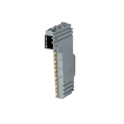
Material number:
X20AI1744-3
Description:
1 full-bridge strain gauge input
Data output rate configurable from 0.1 Hz to 7.5 kHz
Special operating modes (synchronous mode and multiple sampling)
Configurable filter level
This module works with both 4-wire and 6-wire strain gauge load cells. The concept applied by the module requires compensation in the measurement system. This compensation eliminates the absolute uncertainty in the measurement circuit, such as component tolerances, effective bridge voltage or zero point offset. The measurement precision refers to the absolute (compensated) value, which will only change as a result of changes in the operating temperature.
Short description
I/O module 1 full-bridge strain gauge input
General information
B&R ID code 0xA4EF
Status indicators Channel status, operating state, module status
Diagnostics
Module run/error Yes, using LED status indicator and software
Open circuit Yes, using LED status indicator and software
Input Yes, using LED status indicator and software
Power consumption
Bus 0.01W
Internal I/O 0.5W
Additional power dissipation caused by actuators (resistive) [W] Max. +0.36
Certifications
CE Yes
UKCA Yes
ATEX Zone 2, II 3G Ex nA nC IIA T5 Gc
IP20, Ta (see X20 user's manual)
FTZU 09 ATEX 0083X
UL cULus E115267
Industrial control equipment
HazLoc cCSAus 244665
Process control equipment
for hazardous locations
Class I, Division 2, Groups ABCD, T5
KC Yes
Full bridge strain gauge
Strain gauge factor 2 to 256 mV/V, configurable using software
Connection 4- or 6-wire connections
Input type Differential, used to evaluate a full-bridge strain gauge
Digital converter resolution 24-bit
Conversion time depends on the configured data output rate
Data output rate 0.1 - 7500 samples per second, configurable using software (fDATA)
Input filter
Cutoff frequency 5 Hz
Order 3
Slope 60 dB
ADC filter characteristics Sigma-delta, see section "Filter characteristics of the sigma-delta A/D converter"
Operating range / Measurement sensor 85 to 5000 Ω
Influence of cable length See section "Calculation example".
Input protection RC protection
Common mode range 0 to 3 VDC
Permissible input voltage range (with regard to the electric potential strain gauge GND) on inputs "Input +" and "Input -"
Insulation voltage between input and bus 500 Veff
Conversion procedure Sigma-delta