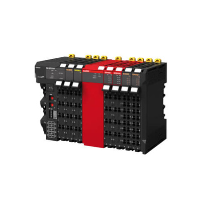
Here is the detailed parameter information about the inputs and outputs of the OMRON NX-OD5256-5 I/O System module:
Output Parameters
Output Type: Digital output.
Number of Output Channels: 5256 channels.
Output Voltage Rating: Typically, it supports a voltage range of 24V DC with a tolerance of ±10%, which means it can operate stably within the range of 21.6V to 26.4V DC.
Output Current per Channel: The rated output current per channel is 0.5A. However, the maximum peak current that each channel can withstand for a short period (e.g., during load switching) is 1A.
Output Logic: The output logic is configurable. It can be set to either positive - logic (sourcing) or negative - logic (sinking) depending on the requirements of the connected devices. In positive - logic mode, the output is high (close to the supply voltage) when the output is enabled, and low (close to ground) when disabled. In negative - logic mode, it is the opposite.
Output Response Time: The turn - on response time is typically less than 1ms, and the turn - off response time is also less than 1ms. This fast response time allows for quick control of the connected loads.
Output Protection: The module is equipped with various protection features. It has over - current protection to prevent damage to the output channels in case of excessive current draw by the load. There is also short - circuit protection to safeguard the module when a short - circuit occurs between the output terminals. Additionally, reverse - voltage protection is provided to protect the module from damage due to incorrect connection of the power supply.
Input - Related Parameters (for Module Control and Monitoring)
Control Inputs: The module has digital control inputs that are used to receive commands from the controller or other devices in the system. These inputs are used to enable or disable the output channels, set the output logic, and perform other control functions. The control inputs are typically compatible with standard TTL (Transistor - Transistor Logic) levels, which means they can accept input voltages in the range of 0V to 5V DC, where 0V represents a logic - low level and 5V represents a logic - high level.
Status Inputs: There are status input pins on the module that can be used to monitor the status of the output channels. For example, these inputs can indicate whether an output channel is currently active (outputting a signal), whether there is an over - current or short - circuit condition on a particular channel, or if the module has detected any other abnormal conditions. The status inputs provide valuable information for system diagnostics and troubleshooting.
Communication Interface: The module is equipped with a communication interface, such as Ethernet or a proprietary OMRON - specific bus, to communicate with the controller and other devices in the I/O system. Through this interface, the module can receive configuration commands, send status information, and exchange data with the rest of the system. The communication interface supports a certain data transfer rate, which is typically in the range of 10Mbps to 100Mbps for Ethernet - based communication, allowing for efficient and timely communication between the module and the controller.